Installing an Analog Podi Boost Gauge - Audi A4
This mod is brought to you by Podi.ca Discuss this mod - Here |
||
| Prior Experience: None |
Use promotional code A4MODS for free shipping in the US |
|
| Cost: approx $100 | ||
| Time: 1 hour | ||
This writeup is meant to compliment the original Electronic Stepper Motor Podi install. This writeup has additional information for installing traditional Analog boost gauges.
|
||||||||||||
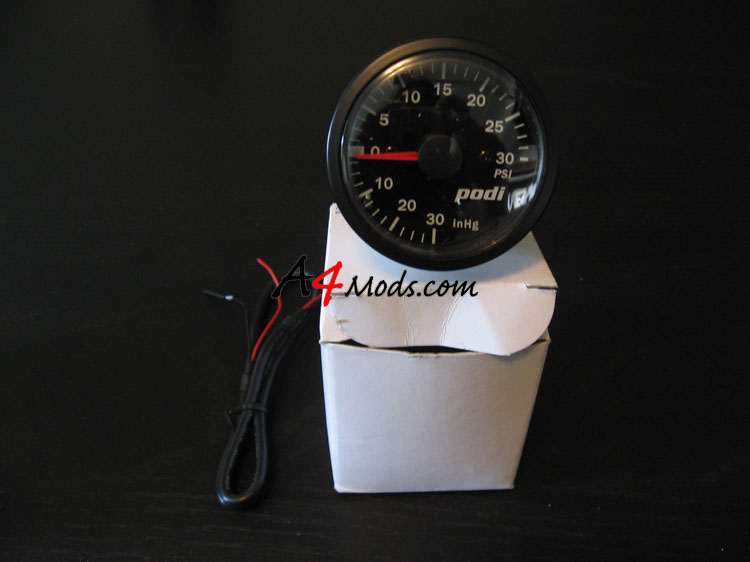
SUPPLIES for Installing the Gauge- Pretty much all of the parts you need are included in the gauge package. I made use of some additional wiring to extend the Podi harnesses. You may not needed these on your install, but I used them on mine. |
||||||||||||
 |
|
|||||||||||
| In this writeup we will be installing 3 different gauges offered at Podi.ca The three different gauges are pictured here: | ||||||||||||
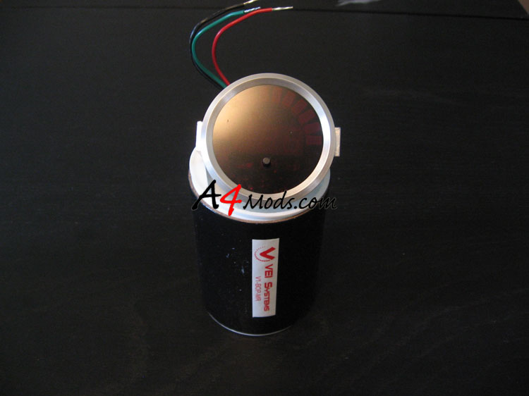 |
VEI Systems digital boost/vacuum gauge in RED. |
|||||||||||
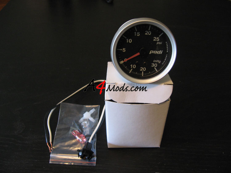 |
Stewart Warner package - this guage has a custom dial and needle to match the Audi Interior |
|||||||||||
|
Podi's new prototype gauge. |
|||||||||||
Part 1a: 1.8T Engine: Connecting the Boost/Vacuum Line
| This small section describes where to connect your Boost/Vacuum Line on a 1.8T engine. | ||
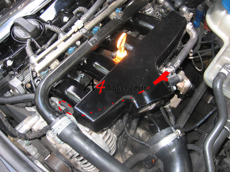
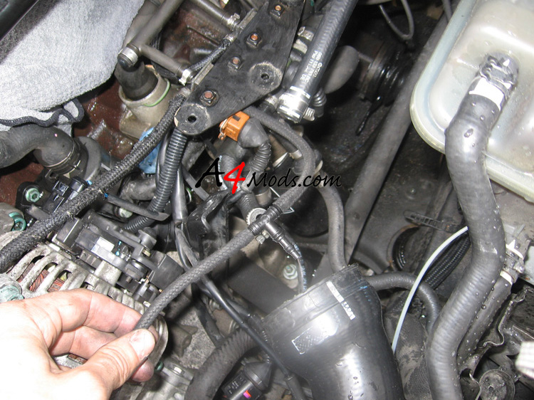
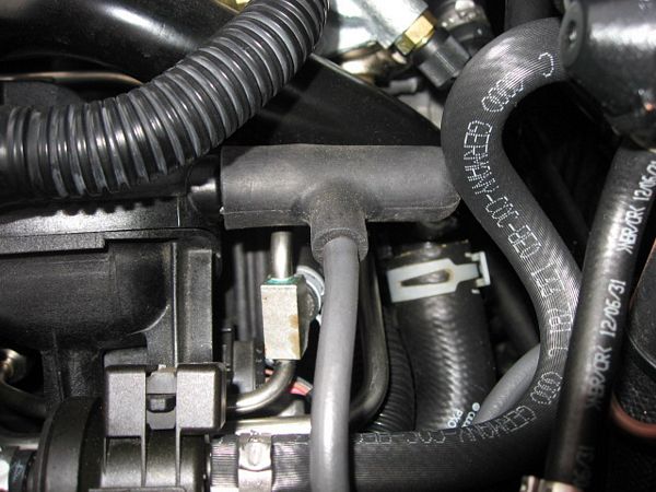
Installing the gauge is not very challenging. The first thing you need to do is find out where to tap to get a good boost reading. I used this line off of the intake manifold. On my vehicle, this line runs under the intake manifold. You can tap it anywhere along the way, but I wanted the tapping point to be out of site. I drew in red the path the boost/vacuum line takes. |
 |
|
 |
I was working on my car doing a couple other things when I installed this gauge, so in this picture my intake manifold was removed. This give you a better idea of where this boosted line runs. I cut the line approximately where the red line is drawn. |
|
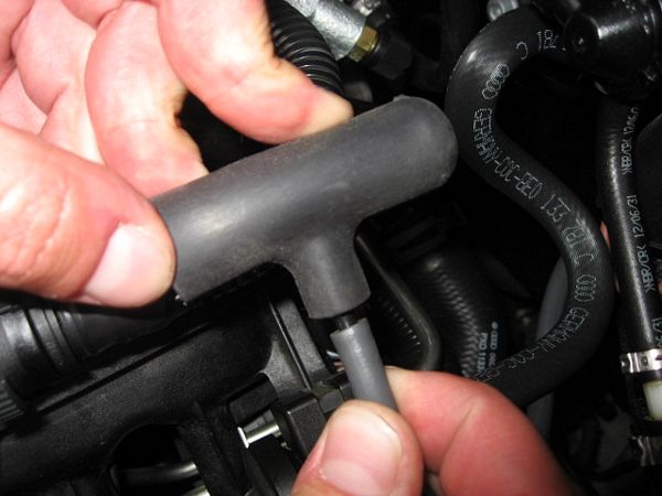
With the line split, you can install the supplied T fitting. I used a little bit of dish soap on the plastic part of the T fitting to get the hose to slip on easier. |
|
|
Part 1b: 2.0T FSI Engine: Connecting the Boost/Vacuum Line
|
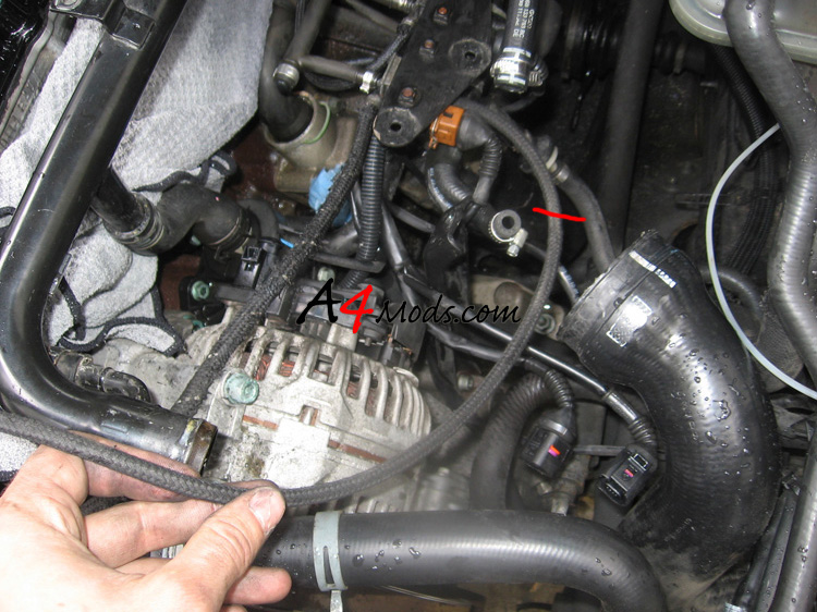
If you have a 2.0T FSI engine, included with your gauge will be a custom silicone piece for connecting your boost/vacuum line. Remove the engine cover and if you look along the right hand side of the intake manifold there will be a small black rubber cap held in place with a clamp. Cut the clamp, remove the small rubber cap and this will expose the bung that you will tap onto. |
||
|
|
|
|
|
|
 |
|
|
Push the boost gauge line as far as you can to make sure the vacuum line seals over the restrictor |
|
|
Slip the open end of the silicone t-fitting onto the exposed bung on the intake manifold and push the fitting in as far as possible |
|
|

Part 2: Connecting the Anti-Buzz Fitting and Wiring the Gauge
 |
||
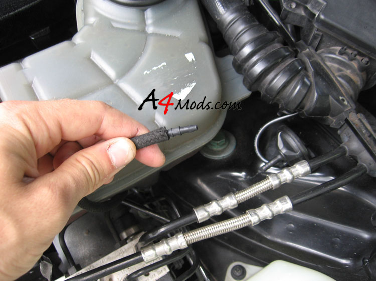
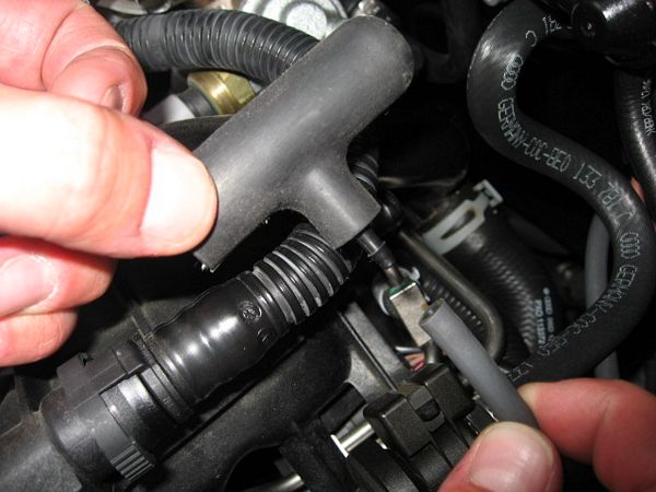
Analog gauges have a tendency to buzz when under boost. To preven this, you should install the anti-buzz fitting on the newly installed boost line. If you have a 2.0T, you have already done this, if you have a 1.8T, you just need to splice this fitting in. After the T you just added, install some vacuum/boost line, and slip the fitting in the end: |
|
|
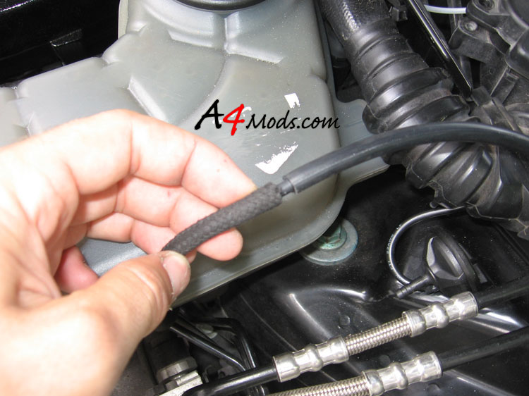
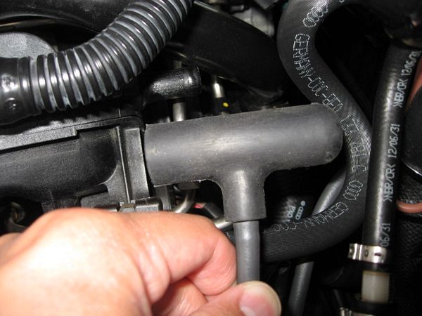
Pop another piece of vacuum/boost line on the end of the anti buzz fitting to feed it into the cabin.
The goal is to have the anti-buzz fitting approximately 14 inches away from the connection to the gauge. |
|
|
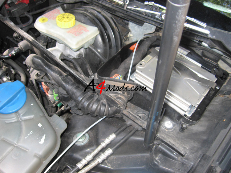
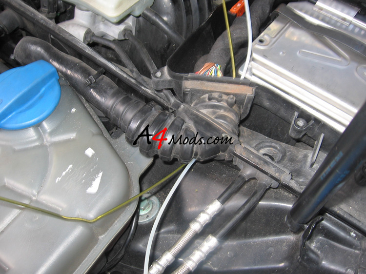
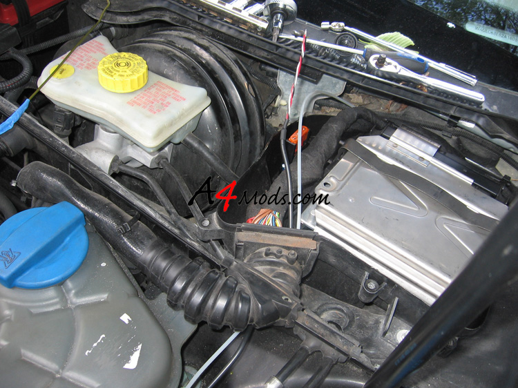
| I decided to run the vacuum hose into the cabin by going through the ECU box. This gives a very easy, straight shot to the cabin. In order to do this, you need to remove the cover to the ECU box. There are only 5 Torx bolts holding in in place. I show how to remove the cover in the ECU Removal Writeup | ||
The picture to the right has the ECU cover removed The path to the cabin is shown in the picture to the right by the white vinyl hose which I used for my old boost gauge. In order to get into the ECU box you need to poke through the rubber grommet/hose which has the electrical connections for the ECU, and then run the wires through it. There are a couple rubber nipples on the grommet which you can try to use, or you can just poke a new hole. This is where your coat hanger comes in handy. |
|
|
 |
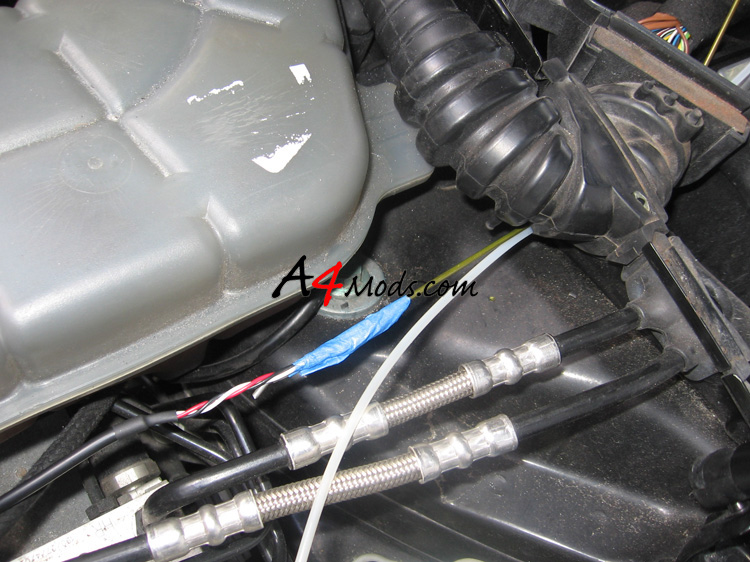
Unbend the coat hanger and poke it through to the ECU box a shown to the left | |
| After the hanger is through, you can tape the vacuum hose to the hanger, and pull it though into the ECU box. I showed this same procedure using the wires for the electronic gauge below: | ||
 |
 |
|
| In order to get the sender harness into the cabin, you need to remove the lower kick panel on the driver's side. This is very easy, and I have this shown in the first few steps of the Turbo Timer Install | ||
After the kick panel is removed, you can look up from the floor on the drivers side and see up and out of the ECU box. Here you can see plenty of daylight coming through. Just slide your boost hose down through this hole so you can access it from under the steering wheel. |
|
|
| The one advantage of the analog guages is that they are very easy to wire. Each gauge only has one power wire, and one ground wire. The power and ground are labelled below for each of the three guages. | ||
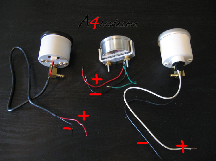 |
||
For a ground, I decided to use the same ground I have been using for all of my accessory installs. I just used a bolt next to the fuse panel. I sanded off the paint to it has a good chassis connection. The black wire from the gauge, and the sender were grounded here. |
|
|
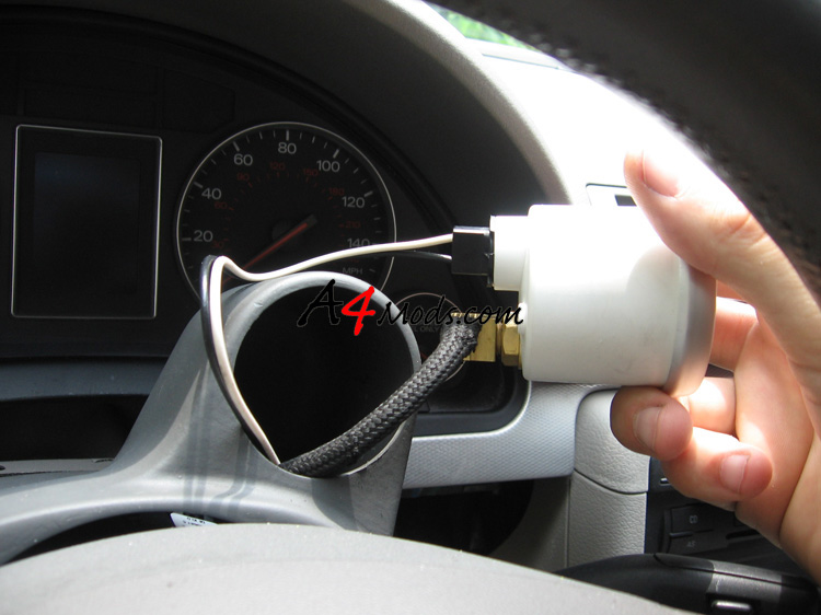
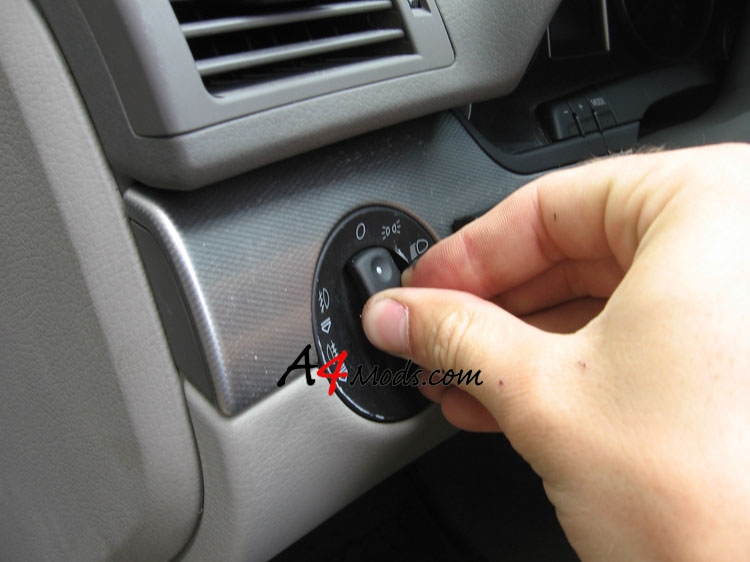
| Powering the Gauge: The power for the analog gauges should be taken from your light switch. By taking power from the light switch, the gauge will dim as you dim your interior lights. | ||
To get at this power wire, push your light switch inwards while it is in the OFF position |
 |
|
|
||
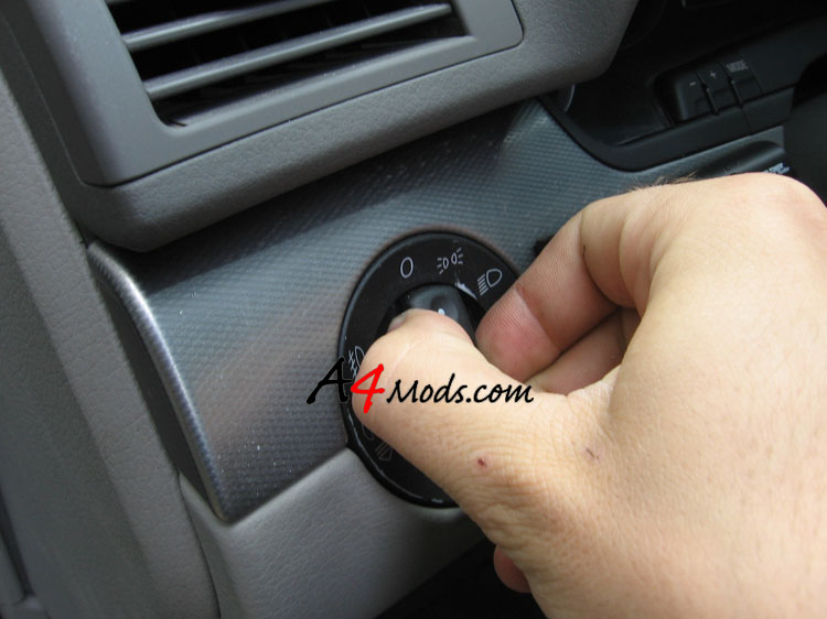
Turn it slightly to the right, between the OFF and the next position |
 |
|
|
||
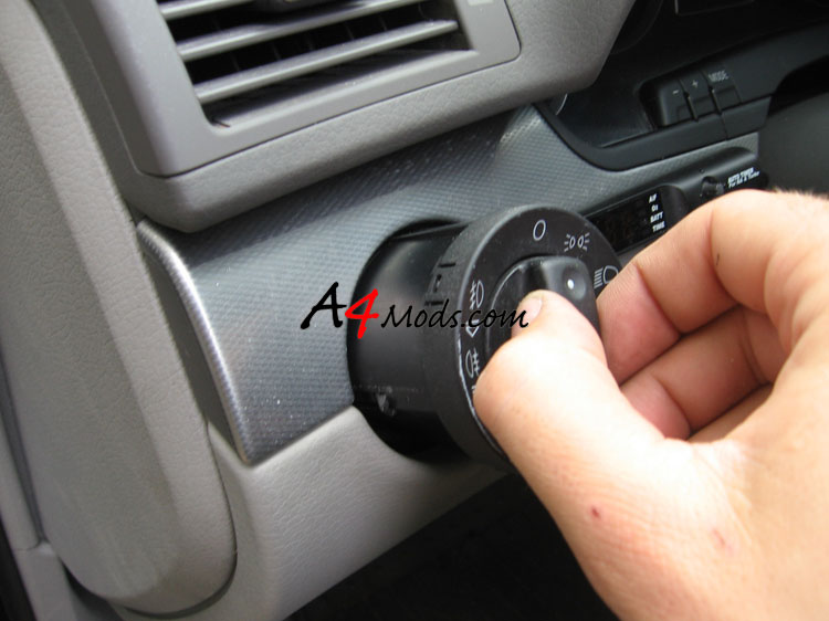
Pull the switch outwards |
 |
|
|
||
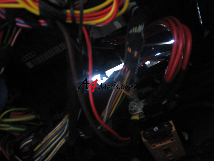
With the switch out, you need to find and tap into the blue wire shown to the right. It is on the left side of the harness. This will be your power wire. |
|
|
| Depending on which gauge you are installing, you now need to run these power/ground wires up into the Podi and connect them to the gauge. Obvously you will have to run the boost line to the back of the gauge as well. When you are done, the back of the gauge should look something like this: | ||
When the two torx bolts are removed, the upper cover will just pop right off of the lower cover. You will see that there is some leather material attached to the upper cover. On my vehicle, there were 4 retainer clips on the underside of the cover which needed to be removed. Just work a small flathead driver in there and they will pop right off. |
|
|
| Push the gauge into the pod, and mount the Pod as discussed in the Electronic Stepper Motor Gauge install. | ||
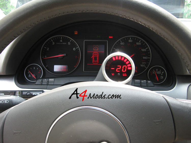
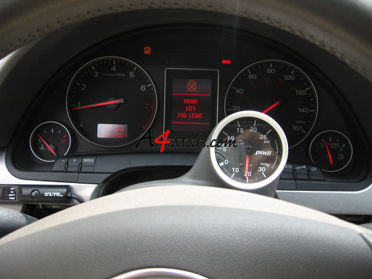
| Here are what the 3 different gauges look like | ||
VEI |
|
|
Stewart Warner |
|
|
Prototype |
|
|
Just because I know you are curious about the VEI digital gauge, I decide to take a short video of how it works when you rev the engine. It is actually much cooler/nicer than I thought it would be. Any other information you may need is located over on the Electronic Stepper Motor Gauge install. |
||